Fuel Pump Controller
New Course!
Practical Introduction to Machine Learning is an online course where you can quickly learn the essentials of machine learning and artificial intelligence.
Limited time free promotion is now available!
It's ideal for managers, business analysts, and developers interested in learning more about this rapidly growing field!
Fuel injection systems run at a fairly high pressure, typically 43.5 PSI. It's about the same pressure as common household water supply. Generating this pressure requires a fuel pump and pressure regulator. Most EFI systems use a return type system in which a mechanical regulator limits fuel pressure and routes excess fuel back to the fuel tank. Typical automotive pumps require as much as 10 Amps average current to operate. Motorcycle pumps require about half as much current. EFI fuel pumps are quite inefficient, very little of the electrical power is used to push fuel. Most of the power is lost in heat.
To reduce power demand and the need for a fuel return line, I decided to design my own electronic fuel pressure regulator. Here's a high level block diagram:
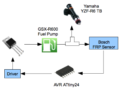
Fuel Rail Pressure Controller
The electronic fuel pump controller operates as a digital control system. Pump pressure is measured by a fuel pressure sensor. A microcontroller monitors this pressure and modulates pump voltage to maintain a constant pressure. A high power MOSFET capable of 35 Amps maximum drain current drives the pump motor. The MOSFET is capable of driving motorcycle or automotive pumps.
The fuel pump controller has gained a fair amount of interest by DIY fuel injection enthusiasts. If you are interested using the controller with your car or motorcycle, an order form is below.
The kit requires basic soldering of through hole parts and connecting wires. Surface mount parts are pre-soldered and programmed on the board, so no special surface mount soldering skills are necessary. Details on the assembly instructions and connections are described below. For more information, send email to madhu@madhu.com
Order using PayPal
Shipping within the continental US is free.
For other locations, visit USPS and select Small Flat Rate Box to determine shipping costs.
A fuel pressure sensor is not included, see below for suitable sensors.
Details
It turns out that many cars use electronic Fuel Rail Pressure (FRP) sensors to control fuel system pressure.
There are several advantages to this system:
- It's returnless
- It requires less power (about 2.5 Amps max)
- A standard motorcycle petcock/inline filter can be used
- Fuel pressure is adjustable
Bosch makes FRP sensors that are used in many Ford cars and trucks. You can find them on eBay or at a junkyard. It appears to have a transfer function that is identical to Freescale five bar pressure sensors. I don't think this is a coincidence.
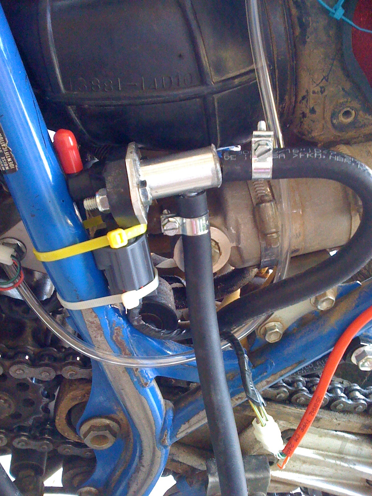
Here's a picture of the FRP sensor mounted on the bike and the control circuit:
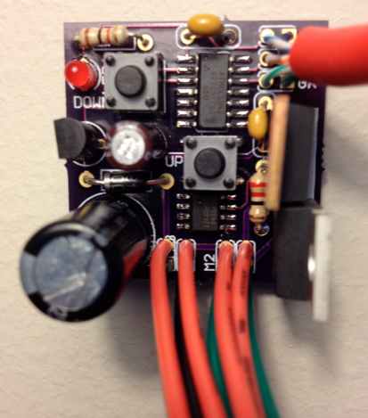
The AVR microcontroller adjusts pump motor speed using a digital proportional-integral (PI) control algorithm. Viscous damping due to fuel flow restrictions obviate the need for a derivative term. The AVR samples system pressure at approximately 8kHz and adjusts pump voltage using pulse width modulation. It maintains constant pressure with only a few percent ripple. It's actually more accurate than a mechanical regulator under certain conditions. Given that injector flow rate is proportional to the square root of pressure, the flow rate does not vary much, if at all.
The pump itself was removed from a 2006 Suzuki GSX-R600 in-tank pump assembly. It's a Mitsubishi UC-T30 that requires roughly 4 amps at 12 Volts. This pump is widely used on motorcycle and some smaller cars. Here's a picture of the original pump mounted on the bike:
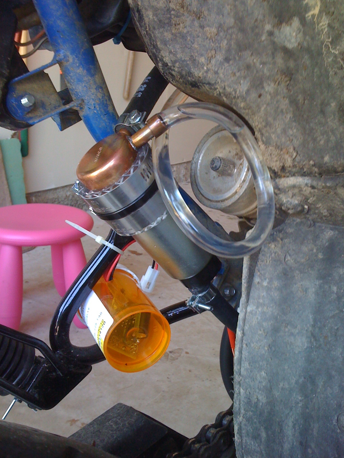
Fuel Pump
One of the ports on the end cap is the low pressure supply from the fuel tank through a standard on-off petcock. The other port is a breather line to vent any trapped air within the end cap.
In practice, the pump controller works quite well. There were two issues with this solution. On hot days (above 90 F), the pump proper can get fairly warm after about 10 mins. This primarily occurs at idle or low RPM when insufficient fuel is flowing through the pump to cool it off. EFI fuel pumps tend to be very inefficient as only a very small fraction of the power they require is used to push fuel. The pump itself can take plenty of heat, it's the gas that can't. Above 120 F, gas near the surface of the pump inlet can boil, which causes the pump to cavitate and lose pressure. The other issue is that pumps usually have a pressure relief valve that can leak slightly, maybe a drip once in a while. While the average pressure is constant, occasional pressure spike can cause the relief valve to drip.
A better solution is to immerse the entire pump in a small tank, that's how most pumps are designed to operate. This way, the pump has sufficient cooling and any drips from the relief valve are contained. I used an aluminum tube 2" in diameter and about 7" long. This works really well.
Bosch 4-pin FRP sensors
Bosch 4-pin FRP sensors are used on some later Ford cars, the 2006 Ford Focus for example.
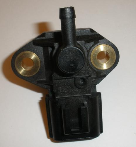
Several Ford part numbers exist:
3F2E-9G756-AD3F2Z-9G756-AC5C3Z-9G756-AA
Ford part 3F2E-9G756-AD has been tested and known to work. The others appear to be identical, but have not been tested. These sensor often appear on eBay with the description INJECTOR PRESSURE SENSOR. They are usually available for low cost.
I have read that this connector will fit the sensors above: Ford P/N 3U2Z-14S411-UC
- Bosch 4-pin FRP sensor
- Pin connections are 1234 left to right looking at sensor pins, fuel port down
- 1 - fuel pressure signal
- 2 - +5v
- 3 - fuel temperature signal
- 4 - ground
- Estimated pressure
- 0.50 volts – 0 PSI
- 1.2 volts – 10 PSI
- 1.65 volts – 20 PSI
- 2.2 volts – 30 PSI
- 2.75 volts – 40 PSI
- 2.89 volts - 43.5 PSI
- 3.45 volts – 50 PSI
- 3.9 volts – 60 PSI
- 4.6 volts – 70 PSI
Ford 3-pin sensors
Earlier Ford cars (2000 Ford Contour, Mercury Mystique, Cougar etc.) use 3-pin FRP sensors. These are functionally similar to the 4-pin Bosch sensors, but do not produce a temperature signal. These are typical part numbers that are known to work:
F8CF-9F972-FF9E26C-84FWC9D29b-830K9
These sensor often appear on eBay with the description Sensor - Fuel Injector Pressure. They are usually available for low cost.
These are the pin connections:
| Ford Sensor Pin | Description |
|---|---|
| 1 | +5 Volts |
| 2 | Ground |
| 3 | Pressure output |
AEM Sensor
The regulator circuit is known to work with AEM sensor part number 30-2131-100. It has a 1/8" NPT male thread:

Alternate sensors
This sensor found on eBay seems to work also. It's nearly identical to AEM sensors at a lower price.
Pumps
In general, most 12 Volt pumps that requires less than 10 Amps maximum tend to work well. I have been told that Walbro GSL series Gerotor pumps are not well suited to PWM controllers like this one. This is because PWM pulses will cause the gears to hammer, fatiguing them. Turbine pumps seems to work well, as long as they are always gravity fed because they don't self prime.
The controller has been tested with Mitsubishi pump model # UC-T30 and pumps from Suzuki LT-R450. The UC-T30 is used in Suzuki GSX-R600 in-tank pumps, as well as other vehicles. For very low power installations, the LT-R450 is a good choice. It requires under 2 Amps max. Even less current will be required when used with the pump controller based on fuel demand. Pumps from the Honda Rincon has also been suggested as another low power alternative.
Also note that in-tank pumps usually have a built-in pressure relief valve that tends to leak a small amount of fuel, so it's best to immerse them in a tank or build a small housing that is full of fuel. This also helps with cooling because these pumps are not efficient and can overheat easily.
Kit Assembly Instructions
Download assembly instructions in PDF format.
Pump controller wiring
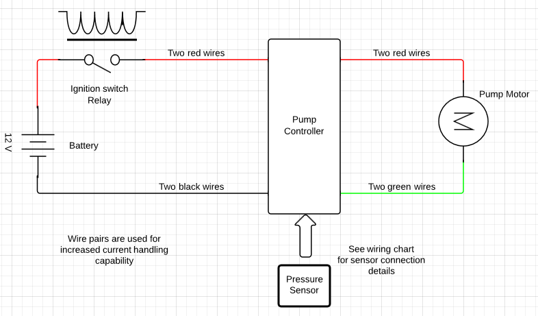
There are two sets of wires. The larger, 20 AWG wires connect to +12 Volt power and the motor. The colored Cat-5 cable connects to the pressure sensor.
Power/Motor wiring:
| Wire | Description |
|---|---|
| Red | +12 Volts |
| Black | Ground |
| Red | Pump motor + |
| Green | Pump motor - |
Power considerations
The black and green wires are in pairs of 20 AWG wire. There are four red wires all connected together. The connections are doubled for higher current capability needed by some of the larger automotive pumps.
The MOSFET that switches the pump on and off includes a heat sink tab. A heat sink with good air flow is recommended, particularly for large high current pumps. If you can comfortably keep a finger on the heat sink tab while the pump is operating, the heat sink is sufficient. If you feel the MOSFET getting warmer than you like, bolt the tab to a larger piece of aluminum. It is even possible to use a strip cut from a common aluminum can if a commercial heat sink is not available. Make sure the heat sink is not in an enclosed container and there is plenty of air flow.
In all cases, avoid connecting the heat sink tab to chassis ground or any voltage source. This could damage the MOSFET.
Sensor wiring:
| FP 1.1 harness | Description | Bosch 4-pin Sensor | Ford 3 pin sensor | AEM sensor | 2006 Ford Focus harness |
|---|---|---|---|---|---|
| Blue/White | +5 Volts | 2 | 1 | Red | Green/Yellow |
| Blue, Brown, Green | Ground | 4 | 2 | Black | Green/Orange |
| Brown/White | fuel pressure signal | 1 | 3 | Green | Green/White |
| Green/White | fuel temperature signal | 3 | No connection | No connection | Orange/Gray |
Normal operation
When properly connected, the LED will flash twice indicating proper operation. If there is no fuel flow out of the system, e.g. injectors are closed, the pump will pressurize briefly (100 ms or less). If the pump continues to run, check for leaks, FRP sensor connections, or low battery voltage. If the pump does not run at all, check pump connections and FRP sensor connections.
Pressure adjustment
There are two buttons, one for pressure increase the other for pressure decrease. Each press changes pressure by a little less than 1/4 PSI. It is initially set to 43.5 PSI. To reset pressure to 43.5, hold the UP button for a few seconds. The LED will blink three times indicating it's back to 43.5 PSI.
Success stories
You read can about fuel pump controller success stories of other installations.
